First Homemade CO2 Laser Built From Scratch

The CO2 laser is one of the most powerful continuous wave lasers available. As a powerful source of continuous energy, the CO2 laser is used for many industrial applications that involve material processing. The CO2 laser produces a beam of invisible energy with unique properties. Unlike laser sources that produce a visible or near infrared beam, the coherent output from a CO2 laser is close to the range of wavelengths that are produced thermally by the human body. Not only is this wavelength totally invisible to the human eye and to ordinary cameras, but it is also completely blocked by most common materials that are transparent to visible and near infrared wavelengths. Glass, for example, is opaque to a CO2 laser beam. For this reason, a CO2 laser can be used to drill, melt, or cut glass; an application that would be inefficient using visible or NIR wavelengths.
This webpage demonstrates a DIY laser, built from scratch, based upon an electrical discharge within a mixture of helium, nitrogen, and carbon dioxide gas.
WARNING: Construction and operation of any laser device is hazardous. Do not attempt to construct or operate a laser without adequate safeguards and safety practices. Most lasers involve high voltages, toxic chemicals, high vacuum, laser radiation and other hazards. The author specifically disclaims any and all liabilities associated with the construction and use of such devices. Designs presented here are in the interests of providing information on operational principles only and do not represent safe nor ANSI safety compliant designs.
Examples of Laser in Action Details of Construction Resonator Mirrors Gas Supply and Mixture Gas Pressure Homemade Optics
Examples of Laser in Action:
(You can click any of the small images to see a larger one)
Laser Beam on Glass Here are some photos that show what happens when the invisible laser beam is focused onto the surface of glass. The glass becomes so hot that it glows with white incandescence. The surface melts. If the laser beam is held into position long enough, the glass will either crack due to thermal expansion, or a hole will be burned through the glass.


Carbon absorbs a lot of optical energy, and reflects very little of it. The two pictures below illustrate this. In the photo on the left, a piece of artist's charcoal sits in front of the laser. The photo on the right shows what happens when the laser is switched on: when focused onto the charcoal, the invisible laser beam heats the charcoal to blinding incandescence.


Wood makes a good target for the beam, and it can often be set on fire without the need for focusing optics


When unfocused, the beam usually causes wood to ignite, or it causes the charred surface to glow red like the tip of a cigarette. When focused onto wood, however, the charred surface appears to respond like artist's charcoal: a tiny point of brilliant white light is produced.


Part 1: Details of Construction
(Overview of Operating System)
The construction of my first successful CO2 laser began after someone gave me some spare glass tubing. Shortly afterwards, someone donated some ZnSe optics. It was at this time that I became really serious about building a working CO2 laser.
I have looked at both the Scientific American and Information Unlimited plans for this type of laser, but the best resource for individual experiences with this device can be found in the home built CO2 laser section of Sam's Laser Faq at http://www.repairfaq.org/sam/lasercc2.htm#cc2toc
I did not follow exact plans to build this laser. The dimensions are mostly arbitrary, based on the parts that were available. The builder can look at various plans and online sources of information, and can then arrive at a general idea of the range of different part types that will work. For example, a high gain laser like pulsed ruby can be used with mirrors that are not designed specifically for it. On the other hand, there are few common materials that will transmit the long wavelengths that are produced by a CO2 laser. With some creativity and a general understanding of the device that is being considered, the builder can construct a laser using the supplies that are easiest to obtain. It is better to understand enough basic principles to enable flexibility when needed. This can save time and money!
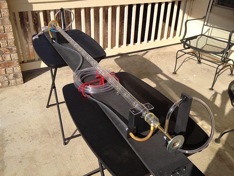
My laser began with a 4 foot section of neon sign tubing. The tubing has an ID of approximately 1cm. For a water jacket, I used a section of fluorescent lamp protector tubing, which is a flexible clear plastic tubing sold to place around cylindrically shaped fluorescent bulbs in order to protect them from accidental impact. I do not recommend using this tubing for anything other than a short laser tube: the reason is that is bends and flexes when water is flowing through it. Glass would be ideal, but irregardless of the type of tubing that is used for the cooling jacket, the construction details given below should still be applicable.
I began by building up a layer of masking tape around the outside of the neon-sign-tubing. This tape is positioned at an arbitrarily equal distance from both ends of the glass tubing. The distance between the two tape rolls will define the area through which the water coolant flows. I gradually built up the tape layers until they fit the ID of the plastic cooling jacket. After this step was complete, I began building up a thin layer of JB weld epoxy along the sides of the tape cylinders (see below).


The tape 'method' did not originate with me. This approach is suggested in the CO2 laser plans from Information Unlimited. However, I have found that the tape method will adapt to a multiple set of circumstances. It can be beneficial with anything that involves centering one cylinder around the outside of a second smaller cylinder. It can be used to join parts that would otherwise be incompatible. Although not perfect, I have used it to fit the tiny output shaft of a small DC motor to the relatively large hole in the center of a CD, when making a small motor driven electrostatic generator. So it can be a reliable method to enable flexibility where a limited variety of parts are available, and where limited tools and funds are available for better alternatives.
Although the tape method is not my own idea, it was my idea to use masking tape for this purpose. Unlike some of the other common types of tape, masking tape is cheap, and it combines evenly as it is rolled onto a cylinder-shaped surface. Once complete, the masking tape roll can be coated with epoxy and sealants in order to provide strength and protection. I coated my entire tape roll with JB weld, and then sealed the outside with shellac. See the pics below for an example. As you have probably noticed in the previous photo, there is a seperate tape-wrap on the tip of the glass tubing. Although it is a bit premature to mention this, it will eventually serve as a spacer to couple the outside of the glass tubing to the inside of a section of copper pipe, which will serve as one of the two discharge tube electrodes. For now, ignore this step. It only became necessary for me to mention, in an effort to avoid potential confusion.


Once the epoxy and shellac were dry, I slid the clear plastic tube over the tape roll. Keep in mind that there was an identical tape roll on the opposite end of the glass tube, and the larger plastic tube was cut in length to match the distance between the outer edge of one tape roll and the outer edge of the other. After the tubing was slid in place, I marked two spots on the outside of the plastic tube with a Sharpie marker, a short distance from the inside edge of both tape rolls. The two spots were marked 180 degrees apart from each other, as determined by the outer circumference of the plastic tube (judging by eye). Small holes were drilled through the locations indicated by these Sharpie-spots, and two 1/4" hose barbs were secured over the holes using JB weld epoxy.


After the water jacket is complete, test it to confirm that there are no leaks! This is very important. Water and high voltage obviously do not mix! I bought a small water pump from a local hardware store. These pumps are used to continuously circulate water for small fountain displays: the small decorative kind used in back yard or small indoor water falls. Use the pump to circulate water through the cooling jacket. In this way, you can spot any leaks that appear, and fix them as needed with additional JB weld. Once all the leaks have been sealed, and the tube has been thoroughly tested with no additional leaks, then you are ready for the next step.
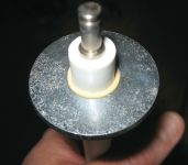
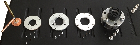
The next major step involves construction of the end piece electrodes. My first such device used 2 nylon washers, a rubber gromet, a section of 1/2" ID copper pipe, and some copper tubing.

This is where you will have the opportunity to benefit from one of my mistakes. Nylon washers were the largest type of washer I could find at the time the original end pieces were constructed. I thought that by doubling them up in pairs, I could provide enough strength to withstand the exerted force required during alignment. I was wrong! So ignoring the fact that these end pieces are nylon, look at the following picture for an idea of how the end pieces are constructed.

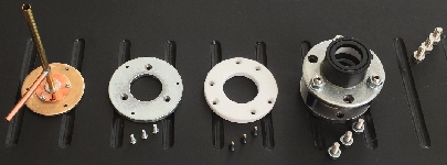
Aside from the choice of nylon washers, there is one additional part in these two pictures that is unecessary. This is the shiny round metal part near the middle in the first photo, and the shiny metal part that protrudes to the right of the nylon washers, in the second photo. This is a part of the original design that I decided not to use, and for now it is irrelevant. However, the 3 bolts are very important. It will be necessary to drill 3 holes through all washers, and then JB-weld three compatible nuts (nuts that go with three corresponding bolts) over the holes on the side with the copper pipe (see photo above). I recommend the use of metal washers. The next steps of this tutorial will show metal washers, which I ended up switching to when I realized that nylon was too flexible. But for now, refer to the photos above as an example, knowing that the final device (if you are constructing it) will need to use metal washers instead of nylon.
To one side of the 1/2" ID copper pipe, I drilled a hole and soldered a short section of 1/4" OD copper tubing. This will become a hose barb. In reality, an actual hose barb would have worked here. However, I chose to use the copper tubing because it was both avaliable at the time, and was compatible with soldering work. JB Weld will probably do here, but be sure and first sand and thoroughly clean all parts to which the JB Weld is to be applied. The dangling hoses that will be attached to these hose barbs will exert some stress on them, due to their length, location, and inevitable movement. It is from these hoses that gas will be fed into one end of the laser tube as air pressure will be drawn out of the opposite end by a vacuum pump.

Some detail of end piece construction is shown above. Most of my work was done using JB weld, but the builder might prefer to use solder, brazing, or welding provided these resources and skills are readily available. Either way, the idea is to get a metal washer centered around a short section of copper pipe. The pipe can be about 3 or 4 inches long. You want washers that are big enough so that you can drill holes and mount the adjustment bolts and screws near the outside edge. At the same time, you want the inside hole to be as close as possible to the diameter of the outside of the copper pipe. My approach was to combine smaller washers with the larger ones, in order to more easily couple everything together. The pictures below show how small washers can be combined with larger ones, in an effort to make the hole in the middle 'smaller' so that it will come closer to fitting around something that will pass through the center. Look at these pictures very carefully, but be aware that they are used only as an example. A range of different sizes can work. The deminsions of these parts should be based upon availability, and how easily they can be adapted to the other parts (like the copper pipe) that you are able to locate.


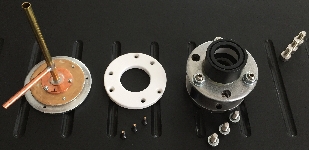
Below is yet another example of how incompatible parts can be made to fit together. Once again, this is not part of the laser that this page covers, so the pictures are used as examples only. 


As you might have correctly guessed, the arrangement above was used in the construction of another laser project. It is very close to what you will be doing (and what I did) for the laser that is covered on this page. Building up layers of tape and using multiple sized washers basically does one thing: it allows the large washers, which are really the most important part of the mirror mounts, to be custom fit and centered onto the electrodes and the actual resonator mirrors. The glass tube that serves as the actual laser bore will be the heart of the whole arrangement. You must design your laser around this glass tubing. The tube is the most important part. The tube can be anywhere from a few millimeters to 1 inch in diameter. Mine is about 1cm to 1/2" in ID. So after you first obtain some glass tubing, you will then need to obtain electrode 'pipes' that can be fit onto the ends of this tubing with reasonable effort. To better clarify, please refer to the pictures below. These pics show how the 'pipe' electrodes were custom fit onto the ends of the glass tubing, with mirror mount (washers) already in place.


As you can see from these photographs, the tape spacer couples the glass tubing to the copper pipe. By looking at the cooling jacket, you can tell that these pics were made before the JB-weld was applied to the jacket. When I built this laser, I did not plan to make a website. As a result, I did not carefully photograph each step in sequence. This is why I am having to 'borrow' examples from other projects in order to provide a semi-complete illustration. I'll admit that this is not very well organized, but next time I will be able to plan beforehand, and take pictures of each step as I go for better clarity. I also made some mistakes in the construction of this first laser, and unfortunately these mistakes are included in the photos. The nylon washers are a good example of this. As a result, I must keep going back and forth between pictures of the actual laser, and pictures of something else that illustrates how it should be done. Please accept my apologies.
Before attempting to attach the copper pipe sections to the ends of the glass tubing, the large metal washers need to be prepared. 
You want to begin by making a single template that matches the shape of these washers. 
You then want to divide the circumference into 3, seperate, 120 degree sections. 
Now you want to place all 4 washers together. Before doing so, seperate the 4 washers into 2 pairs. In both pairs, face the flat sides together. After doing so, put the two pairs together and put some masking tape on opposite ends as shown below. 
Now you want to wrap some masking tape tightly around the outer circumference of the washers.

Now cut out your template. The template should be an exact fit when placed over the top of the washer stack. At a predetermined distance from the edge, put a mark along all three lines that divide the 120 degree sections. 
Using a sharp point, make three holes through the template, at the three marks. Place the template over the washer stack, and use a suitable writing instrument to put marks on the washer beneath these holes. 
Using a drill press, drill a small hole through one of the marks. 
After making the first hole, insert a nail or some other metal object that provides a snug fit. Repeat this procedure after making the second hole. In this way, the individual washers are better secured against misalignment while drilling. 
It is important to remember that the washers are arranged into pairs, with each pair having the flat sides facing (the individual washers should have one side that is obviously flatter than the other side). Because the holes might not be precisely 120 degrees apart and precisely positioned at the same distance from the edges, you will want to keep the individual pieces from getting mis-matched; in other words, you will want to keep four pieces paired as they were when you drilled your holes. To avoid getting them mixed up, I marked one pair as "A" and the other as "B". This will become important when these washers are fixed to the end pieces that they are being designed for. Aside from keeping the washer pairs separate and consistent, there is also the need to keep them from becoming rotated away from the position that they were in when the drilling procedure was performed. To ensure that this detail is not overlooked, I marked one of the three holes, on all four washers, with a sharpie. This enabled me to ensure that these holes were lined up radially in the same way that they were during the drilling process. See the picture below for an example of this

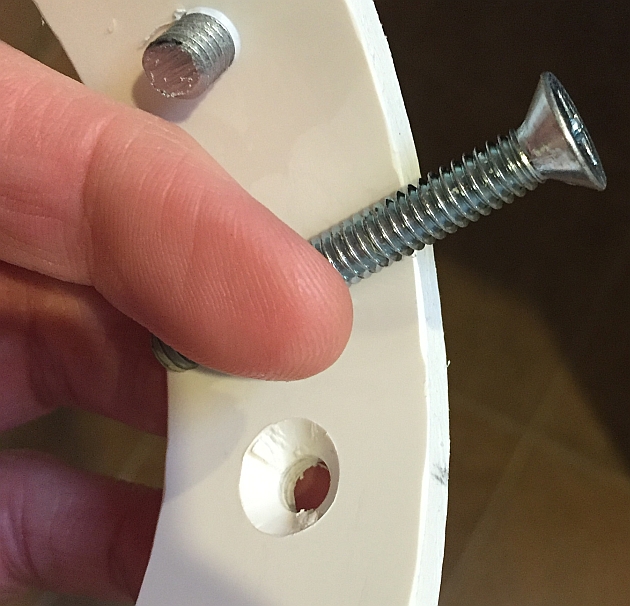
The next step involves the adjustment bolts and threading. You will want to sand and clean one side of one washer, from each of the two pairs. Because the two flat sides were positioned facing each other when drilling the pairs, you will want to sand one of the curved sides (as opposed to the flatter side) on the piece that you choose from each of the two pairs (see below).

The side that is sanded will eventually face the glass tubing that extends from one electrode to the other. Take one pair of washers and insert three hex-head bolts through the three pairs of holes. Tighten three nuts onto these bolts, on the sanded side of the washer pair. Apply JB-Weld epoxy around these nuts, allowing the epoxy to come in contact with the sides of the three nuts. Be careful not to allow any of the epoxy to get onto the bolts, on into the threads. All surfaces to which the epoxy is to be applied must be free of oil and dirt, including the nuts. Before applying, soak the nuts in alcohol to remove any oil or grease residue. Allow the nuts to dry before applying the epoxy.
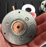
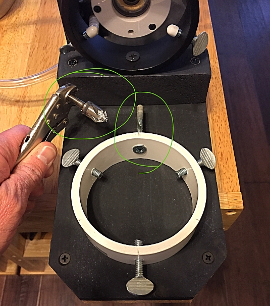
Once you have two pairs of washers that fasten tightly together using six hex bolts, then you are ready for the next step. The holes in the middle of my washers were much larger than the outside diameter of the copper pipe sections used for electrodes. The holes were also significantly larger than the outside diameter of my resonator mirrors. So I needed some way to 'step' these holes down, before taking up the slack with the tape method. The tape method would probably be acceptable for creating a spacer between one washer from each of the two pairs, and a corresponding copper pipe electrode; but I preferred something with a smaller profile for the purpose of mounting the resonator optics. Look at the picture below. You will notice that a small additional 'insert' washer was placed over the center of the larger washer. This 'insert' washer takes up the space between the larger washer and the tiny output mirror.

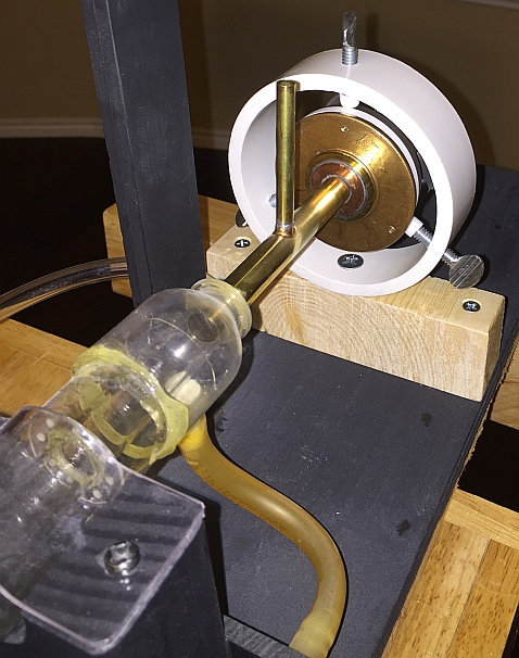
Below is a diagram showing the basic setup. The output mirror must be in line with the opening of the copper pipe. The three adjustment bolts are tightened against an O-ring. The O-ring serves as both an air-tight seal, and resistance against which the bolts are tightened seperately to provide mirror alignment.

Once the basic structure is complete, you will need to apply a source of vacuum in order to check for leaks. This is where the frustration can begin. If your tube is sufficiently sealed against leaks, you should be able to create a glowing discharge within the length of the glass tube using a neon sign power supply. The distance between my electrodes (the arc length) is about 48 inches, and I am using a 15kV, 60mA neon sign transformer. When you pull the pressure down using your pump, the tube should look like a neon sign when power is applied, except not as bright. Instead of the brilliant orange light characteristic of neon, the tube should produce a pink discharge. The glowing discharge should appear to fill most of the tube cross section. If you obtain a weak purple discharge that is brighter near the ends of the tube, then you have leaks. The weak purple discharge (or complete lack of discharge) indicates that the pressure is too high for the voltage that is provided by your power supply. Under these circumstances, the system will not work as a laser.
For leak detection, I use a fish tank air pump. I pump air into the laser tube using one hose connection at one end of the laser tube, and I seal the other end which is intended for the opposing hose connection. In this fashion, air from the tiny pump is forced into the laser tube and out through any leaks that are present. Using a small brush, I apply soap water to all joints and surfaces of potential leakage. Leaks will be indicated by bubbles which form after the soap water is applied to a suspect location.
Part 2: Resonator Mirrors
Zinc Selenide
Based upon gain and active length of any given system, most laser types require mirrors in order to increase the virtual length of the amplifying medium, and to keep the physical size and power supply requirements within manageable limits. Fortunately, CO2 lasers have high gain when compared to most other continuous wave laser types. Although mirrors are needed for a practical system, the requirements for quality and precision can be quite forgiving when compared to the optics that are needed for most other types of continuous wave gas lasers. As mentioned before, there are few materials that transmit the 10.6 micrometer wavelength of this laser. Materials like glass, which are transparent at visible wavelengths, are totally 'black' to the CO2 laser output. One of the best materials for CO2 laser optics is Zinc Selenide (abbreviated ZnSe). ZnSe has good transmission at 10.6 micrometers, and it does not absorb moisture as do some of the other choices for CO2 laser optics.
A partially reflective ZnSe output coupler will transmit and reflect energy in the 10.6 µm range. As with any laser, the transmitted portion becomes the output beam while the reflected part undergoes further amplification. In theory, it is possible to use two plane (flat) mirrors (with one of them being the reflective ZnSe output coupler). In practice, proper alignment is more easily attained if at least one of the two mirrors is concave.
The Alternative
It is possible to construct a working CO2 laser without the aid of transmissive optics. In this case, a small opening must be provided in order to pass the output beam. A mirror with a small hole thus serves as an output coupler. The hole is sealed with a material that is capable of transmitting the output. This has been a subject of much interest to me - appealing in terms of possible optimization. As such, the builder would become more independent - free of the burden and expense of locating and purchasing specialized optics.
Fortunately, ordinary salt has good transmissive properties at the CO2 wavelengths. With a hole coupler (opaque mirror with a hole to pass the output beam), a sliver of rock salt can simply be epoxied over the outside opening of the hole. Such an approach was explored in my so called "Gilligan's Laser" and "Poor Man's Laser", as featured in the clips below:
Part 3: Gas Supply and Mixture
The laser will run on a mixture of helium, CO2, and nitrogen, or it will run on ordinary exhaled breath! Helium significantly enhances laser performance. CO2 and nitrogen are the only two gasses that are absolutely required. The laser will run with air that is simply exhaled into a balloon, because nitrogen and CO2 are present in exhaled breath.
If I'm using an actual gas supply as opposed to just running the laser on my breath, I first deposit a small amount of carbon dioxide into a balloon. I measure the circumference of the balloon using a tailors measuring tape, and then use this circumference to calculate the volume. I want the final mix to be composed of about 10% carbon dioxide and 20% nitrogen, so I multiply the volume by 3 (in other words, 3x the volume of CO2) and calculate a new circumference. I then add nitrogen to the balloon, until I arrive at this new circumference. At this point, I divide the last volume by 30% (assuming I have twice as much N2 as CO2), and then calculate a final circumference using this number. Following this last step, I inflate the balloon with helium until this final circumference is reached. In this way, the 3 gasses can be combined in a predetermined ratio with some accuracy. Sure - the balloon is not a perfect sphere, but this method is much more accurate than simply guessing!
Helium can be obtained at Walmart in the form of a party balloon kit - cost around $20. Air should be fine for nitrogen, although welding nitrogen would probably be better if available. CO2 can be obtained from dry ice, or by mixing baking soda and vinegar.
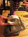
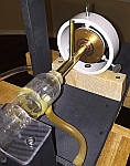
Take a mason jar and punch a small hole in the lid. Obtain a turkey baster, remove the bulb, and secure its wider end over the hole in the jar lid - use epoxy to secure and seal the turkey baster onto the lid. Any nozzle will work as long as you can slide a balloon over the end for inflating. In one of the following examples, I have one jar lid with a turkey baster nozzle, and the other lid with an old helium tank nozzle. Click on each picture to view details that should make the simple arrangment quite clear.


Once you have a nozzle secured and sealed over the hole in the jar lid, sprinkle some baking soda in the bottom of the jar. Fill a small cup with vinegar and put the cup inside of the jar. Put the lid on the jar. My own version is shown below (any plastic or rubber object with a hollow taper should work here, as long as a balloon can be snugly fit onto its tip).

To obtain carbon dioxide gas (as called for in #1, on my Gas Mixing Technique), see the example below:
It's best to begin with the gas that you have the least control over. If I'm mixing baking soda and vinegar to make CO2 (which can be quite messy), then I allow the reaction to produce the gas quickly and fill the empty balloon. After the reaction has slowed down considerably, I remove the balloon and base everything else upon the volume of CO2.
If the only way you can get helium is to bring it home in a party balloon, then you'll obviously need to begin with the helium (just make sure you don't tie the balloon in a knot, so that you still have access to the opening of the balloon - a special request you might need to make to the clown who's inflating it). It's a ratio. Regardless of which gas you begin with, you want roughly 10% Co2, 20% N2, and 70% He. Air can be substituted for nitrogen - I normally just use air.
You're going to measure the circumference of the balloon in order to calculate it's volume, and then your going to base your percentages (of each gas) off of this volume. The circumference just allows you to make measurements, and the volume is what you base your calculations on.
If your helium is already in a balloon when you get it, then just calculate everything else around the helium. In other words, the gas you begin with is going to determine how much of the other two gasses you need.
Let's have a look at an example. Let's say you come home from the party store with a balloon full of helium. Measure the outside of your balloon with a measuring string (the first step will require that you measure the circumference of the balloon and then calculate its volume) - lets say you get 40cm. Before you can calculate the volume of the balloon however, you must find its radius.
C=2πr
solving for " r ", we get
r = C/2π
r = 40cm/2π = 6.4cm
Now that we have the radius, we can calculate the volume.
V = (4/3)πr3
= (4/3)(3.14)(6.4cm)3
= (4.19)262cm3
Volume of helium = 1098cm3
So now we know that our balloon has 1098 cubic centimeters of the first gas, which is helium. We know that when the three gasses are combined in the balloon, we want the helium to be 70% of this total volume. We can find the total volume by dividing 1098/70%, or 1098/.7 = (approx) 1570. So our total volume will be 1570cm3.
The difference between the total volume and the volume of helium is 472cm3. Since 10% of the total gas is CO2, we can find its volume by simply multiplying 10% by 1570cm3, which gives us 157cm3. Nitrogen, just multiply 20% by 1570cm3 which give us 314cm3. So thus far, we have:
- Volume of He = 1098cm3
- Volume of Co2 = 157cm3
- Volume of N2 = 314cm3
- Total volume = 1570cm3
Notice that you get ever slightly different results when you add the volumes individually, as opposed to multiplying the total volume by the individual percentages. Don't worry about this! None of it has to be this precise. Even the 70/20/10 % ratio varies depending upon the source of literature that you refer to. Besides, variations are inevitable when rounding off numbers - especially when numbers are squared or cubed.
At this stage, you have a balloon filled with helium. The outside of this balloon measures 40cm. Our calculations tell us that this balloon has a volume of 1098cm3. In order to determine how much gas to add in order to obtain the required volumes of Co2 and nitrogen (remember, we've already calculated their respective volumes), we need to calculate (as opposed to measuring) the circumference for the helium plus the next gas that we plan to add. For the sake of this example, lets just assume that we're going to add CO2 next. We know that CO2 is only 10% of the total, or 157cm3. So let's add the two volumes together (He + Co^2), which will give us 1255cm3. Now let's find our radius (remember that when we measured the circumference of the helium, we had to go through a few steps to find the volume - now we're going to do just the opposite by using the volume to find a new circumference)!
V = 4/3πr3
solving for " r " gives
r = 3√ V/( 4/3π)
= 3√ V/( 1255cm3/4.187)
= 3√ 300cm3
r = 6.69cm
So now let's find that circumference!
C = 2πr
= (2)(3.14)(6.69cm3)
C = 42cm
With your tailors tape wrapped around the balloon, you're going to insert CO2 until the balloon expands from 40cm to 42cm in diameter.
For the remaining gas, we need only to find the circumference for the total volume of all 3 gasses. So repeating the last series of steps ...
r = 3√ V/( 4/3π)
= 3√ V/( 1570cm3/4.187)
= 3√ 375cm3
r = 7.211cm
C = 2πr
= (2)(3.14)(7.2cm3)
C = 45cm
Now, just fill the balloon with nitrogen (or air) for the final step, holding the measuring tape in place as before, until the tape indicates that the balloon circumference is 45cm. That's it! You're done!!!
Part 4: Gas Pressure
Now for the voltage to pressure ratio ... I believe Prof. Mark Csele [1] told me that optimal pressure to voltage ratio was something like 15 or 16v/cm*T. For an example, assume 120cm electrode separation (about 4 feet, like my first laser) and a 15kV power supply. 15kV/120cm = an electric field intensity of 125 volts/cm. Applying this to the optimal voltage pressure ratio:
125v/cm * cm*T/16v = ~ 8 Torr needed for optimal conditions, using a 15kV power supply with this electrode separation.
That's a theoretical guideline. In practice, you'll likely need to experiment with variations of this guideline in order to obtain the very best results. The most important part is a tip I received from Professor Mark Csele: just gradually decrease your tube pressure via needle valve until an electrical discharge begins. It is at this pressure (or barely below it) that lasing occurs! This is more important than theory, when it comes to an actual working laser. Too much pressure and your power supply obviously will not overcome the resistance of the gas. But less obvious is that lasing occurs at the pressure where the discharge begins (and within a pressure range that extends just slightly below it). You don't need a pressure meter for this - just open the needle valve until the discharge starts! Keep it around that range. It's that simple, assuming that you've got a workable device and assuming that other factors are adequate.
Be sure that there is a considerable length of hose between your pump and your laser. Put a backup bottle, or a separate valve that you can shut off before turning your pump off. If you don't, then pump oil will back up into your laser (and hose) when you turn the pump off.
Make sure there is a long length of hose between your laser and everything else - You want the hose length between the laser and everything else, such as pumps or needle valves, to be considerably longer than the distance between your electrodes! This is very important. Otherwise dangerous electric current supplied to the laser electrodes can easily bypass the laser tube, and instead travel to nearby hardware through the partially evacuated pump hose. In this way hardware, such as a needle valve, can become electrically live. Such a situation can very easily result in lethal electrocution. Take your time, take care, and be safe! Live to see your laser completed, and to build another!
Using a bottle of baking soda and vinegar (to produce CO2), I was unable to see any improvement by adding nitrogen gas. The helium was the most important factor. Residual air in the bottle (mason jar) was enough to satisfy the need for nitrogen. The helium and CO2 were the most important parts - you basically want more helium than CO2. Without the helium, lasing is quite poor. Keep in mind that my first laser had an electrode spacing (active length) of 4 feet, so the resulting gain somewhat compensated for flaws that could have resulted in a non-working laser, had I chose a shorter tube design. Forget about lasing breath without helium. I'm not saying it cannot be done (I probably did, but I don't remember now) - I'm just saying this is not a "first" attempt recommendation.
CO2 Laser 2
My second CO2 laser used a glass tube that was around 75cm in length, and only 6mm in inside diameter. A pair of PVC compression fittings were used to seal the ends of the water jacket. The water jacket itself was just a plastic tube retrieved as a container for a set of welding/brazing rods, as supplied by a local hardware store. The compression fittings were 'custom' fitted with O-rings, to better seal against leakage near the ends of the water jacket. The end electrodes were made using brass compression fittings. The brass compression fittings were also custom fit with O-rings, for the purpose of sealing the tube. See the drawing below for details.
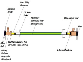
My second CO2 laser was merely a practice exercise for the third. True success was realized with my third device. The second one was too difficult to align, given the narrow bore. With persistence, I could have aligned it properly, but I lost interest and simply built another laser using the same brass and PVC compression fittings.
The use of brass compression fittings, was an idea I borrowed from researcher Jon Singer. Jon Singer had used them in a similar fashion, except with dye lasers that he was building.
CO2 Laser 3
Laser complete - page content (write up) under construction.
CO2 Laser 4
As with my "Gilligan's" and "Poor Man's" CO2 lasers, CO2 laser number 4 is being designed with an emphasis on very basic and readily available materials. Unlike the two designs mentioned above, number four is an attempt to obtain performance that I hope will rival that of my first and third designs. Remember that the first and third designs used a proper ZnSe output coupler. The use of 'real' laser optics, via a ZnSe output coupler, permits performance similar to that of commercial laser devices. In the Gilligan's and Poor Man's designs, a hole with a salt window is used to pass the output beam. Mirrors at both ends of the laser tube must still be aligned, but one of them has a small opening to pass the output beam. In order to optimize such an arrangement however, I believe it is necessary for at least one of the resonator mirrors to be concave. The idea is for the amplified laser energy to gradually converge with each pass, eventually passing through the small hole that is centered within the diameter of one of the mirrors. The Gilligan's and Poor Man's devices use two plane (flat) mirrors. My expectation is that in using a wider bore (laser tube) and concave mirror, I will be able to better make use of the entire active area of the laser discharge. Poor Man's and Gilligan's used a bore of only 6mm (in one case) and 1/2" in the other. Number 4 will employ a 1" wide laser tube. The tube is comprised of an ordinary T8 fluorescent lamp bulb, and the water jacket tube is made from a T12 fluorescent lamp bulb.
A long focal length concave mirror will be hand ground, using the Dobsonian mirror making technique. The Dobsonian technique is a method used by amateur telescope builders. I decided to attempt this technique with copper instead of glass, for three primary reasons: copper is much softer, and therefore easier/faster to grind than glass, copper has good reflective properties at the relevant wavelength, and glass must have metal sputtered onto it (a non trivial process in and of itself). The fabrication of copper mirrors, for this specific purpose, is currently under investigation by physics instructor John Gates. Mr. Gates and I are working together on this project - he is developing the mirror making technique while I am constructing the laser tube. Mr. Gates has already made some very significant discoveries regarding this process. I will share his success and progress as it develops - his work being an essential contribution to the overall design.
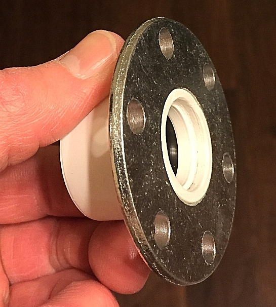
Here is my part of the construction, as currently underway:


As with my first laser, steel washers are drilled with strategically positioned holes in order to accommodate a three point adjustment plane. One of the washers is secured to an aluminum pipe using JB weld epoxy, and sliver paint is then applied to the epoxy for aesthetics. A hole is drilled in the electrode tube to accommodate a hose connector. Each of the two electrodes must have a hose connector - the vacuum pump will be connected to one hose connector and the gas supply will be connected to the other.

In my first design, the end pieces are coupled around the outside of the glass laser tube. Because the electrodes are on the outside of the laser tube, the cooling jacket does not extend far enough to accommodate them - so the section of tubing, between the electrodes and cooling jacket, becomes quite hot. In a slightly different approach, the current project uses high temperature aluminum tape to space an additional section of tubing, serving as a coupler, to the aluminum electrode (the part with the steel washer flange) and the glass laser tube (see below).


The prepared coupler is then used to join the electrode/mirror adjustment holder to the laser tube:

For the hose connector, I just used a 1/4" ID aluminum tube. The tube is joined and sealed over this hole using epoxy. A hole size is chosen that will enable the aluminum tube to be partially inserted into the electrode tube wall without extending beyond it. Basically stated, the hose connector tube must simply be snug enough to remain in position until the epoxy has had time to cure (see picture below). I used fast dry epoxy to partially secure the hose connector, followed by powerful JB weld (slow type) epoxy.


The top of the end upright stand has a hole strategically positioned to accommodate the hose connector. The top thus serves as a brace for the hose connector, resulting in a more rugged design.


Physics instructor John Gates contacted me around 2013 for help in building a CO2 laser. Like myself, he liked the idea of building a laser using cheap and readily available supplies. He introduced the idea of using a computer hard drive platter for an output coupler. Hard drive platters are made of metal, thereby eliminating the headaches associated with drilling and cutting glass. I told John that I had been thinking about grinding my own high reflector mirror using the Dobsonian telescope mirror making technique. He immediately began working on this and quickly came up with a wealth of experimental results. Almost over night, John developed a detailed set of guidelines based upon his experience. Here is a tutorial John Gates prepared, based upon his experiments.
HOW TO GRIND, POLISH, & TEST COPPER PENNY MIRRORS for CO2 LASERS
Introduction:
It almost defies belief that a laser, capable of producing dozens of watts, can be made almost entirely from scratch. You've seen videos of carbon dioxide lasers burning holes through wood, and you want one. You can buy a sealed unit from Ebay (expensive) or you can build one out of junk (awesome). Everything about the CO2 laser looks doable until you get to the optics. A zinc selenide output coupler is expensive and sometimes difficult to locate - like a high voltage capacitor needed for that Tesla coil you've been wanting to build; rare and expensive. But for a homemade Tesla coil you can construct your own capacitors, using beer bottles and salt water, for practically nothing. Likewise, you can grind and fabricate you're own optics for a homemade CO2 laser! The output coupler can be as simple as a section of shiny metal that has been cut away from a hard drive platter, with a small hole that has been drilled and covered by a rock salt crystal. The HR mirror needs to be concave for good performance, and can be ground from a penny and some auto body rubbing compound. Save your money for what is really needed - a decent HVAC vacuum pump and/or NST.
PREPARATION:
You'll need the following:
two pre 1983 pennies (100% copper) or aluminum hard drive platters (NOT the glass or ceramic type) two 5/8" hex bolts epoxy (quick acting gel preferred - I used 6 min set time) salt & vinegar sandpaper in the following grits (80 to 600 grit or finer) Turtle Wax RUBBING compound (the red labeled jar found at car part stores)
- Clean two pre-1983 pennies (100% copper--no zinc inside) with dish soap & a scrubby. If you are using hard drive platters, sandwich one between two pieces of wood and use a hole saw to slowly cut two disks. The disks are already clean and flat, so you can skip the following steps.
- Place pennies in a vinegar & salt solution to further clean/brighten pennies (not too long though, about five minutes).
- Rinse the brightened pennies and then roughen a face of the 5/8" hex nuts with 80 grit sandpaper (epoxy holds better).
- Clean the prepared bolts with some rubbing alcohol then epoxy pennies head side down. Make sure the pennies are centered and firmly contacting the nut. I applied thoroughly mixed epoxy with a toothpick to the perimeter of the penny. To guarantee a solid hold, I used a toothpick to apply a little epoxy around the sides of the penny. If using hard drive platters, just epoxy a large hex nut to the back after estimating the center. When the epoxy hardens, clean up the sides and move onto "grinding and polishing"
- Allow the epoxy to cure overnight (we want a really good hold).
- Working on a glass surface (because it's incredibly flat) grind flat the tail side working through 150 to 600 (or finer) grit sandpaper. In the beginning, straight dragging strokes instead of circular strokes work best. Get in the habit of rotating the pennies and sandpaper to introduce a little randomness (which is good). As the grit size get's smaller (around 220, 320), use circular strokes.
- After your finest grit, dispense with the sandpaper and use the Turtle Wax rubbing compound directly on the glass surface. You'll notice the sides are a little rougher and the center smoother. As you flatten the pennies you'll see a "halo" move out to the sides as the center flattens out. Even though we are working on glass, the pennies are actually slightly convex. Keep flattening/polishing with circular strokes until the halo moves beyond the sides.
- This step is important. Otherwise, "grinding & polishing" can become confusing. Place your newly flattened pennies on 600 to 1500 grit sandpaper and give a few strokes to matte the surface. Yes, you just destroyed that nicely polished flat penny, but you'll need this matte finish later.
- Pick which flattened penny you like the best, it will become the concave mirror (HR) in your laser and the other will become the "tool" (a nice convex mirror if you ever need one).
GRINDING & POLISHING
You'll need:
the two previously flattened pennies epoxied to 5/8" nuts (or aluminum hard drive platters epoxied to nuts) a small drill press vise (this vise is flat on the bottom and meant to be bolted to a drill press, a five pounder is good) Turtle Wax RUBBING Compound (the brand is not important but it must be rubbing compound - polishing compound takes a longer time) paper towels plenty of free time, a good movie, a good wife, and a sandwich wouldn't hurt CAUTION!: Do not use buffing sticks (emery, tripoli, white or red rouge) meant for cotton buffing wheels mounted on bench grinders. Although the grit is good the wax binder is awful and will cake-up and cause slipping which equals scratching. I haven't tried real grits used to grind telescope mirrors but they may work. Remember grit size determines focal length. It is really easy to grind in a curve that is too deep. I would go straight for the cerium oxide or rouge. We are only removing ten-thousandths of an inch from the center!!! It's better to think of polishing out a mirror NOT grinding out a mirror.
- Clamp down the tool into the drill press vise. Smear a little rubbing compound onto the tool and onto the would-be mirror. Avoid clumping and swirl it on for a nice even coat. Why not use polishing compound instead? In my experience, the super fine grit/paste of the polishing compound does not prevent copper-on-copper contact which results in gouge-like scratches! The red rubbing compound never fails, and it polishes out quicker.
- The following steps are very important and will take experience in order to master. Place the mirror directly on the tool and slide it directly back & forth, center over center. Start with a little pressure to smear the abrasive then build up to a moderate amount of pressure. The overhang should be a quarter or less of the penny's diameter. You should feel a moderate amount of resistance, but it should still feel smooth with good contact over the entire surface (stop if it's not smooth or scratchy and clean). When you get good at it, it feels like you are vibrating the mirror over the tool - not too fast though. The tool (the bottom penny) is becoming convex and the mirror (the top penny) is becoming concave. This happens from the center out. What you are doing is called the normal stroke - a term used by telescope mirror makers. Springfield Telescope Makers, Inc. has an excellent online guide which clearly and thoroughly explains this technique.
- Perform 5-10 normal strokes and then, without lifting the mirror off the tool, rotate the vise a little counter-clockwise and the mirror a little clockwise. Apply 5-10 more normal strokes. Rotate. 5-10 more strokes if possible. When the pennies start to bind up, you'll notice a lot more resistance, so stop. Clean with a paper towel, reapply compound, and begin again. Trying to push it too far with a lot of resistance will result in clumping of the abrasive which will give you scratches. When you clean the pennies, you should have to fight a little "suction"/adhesion to get the mirror off the tool, and you should see a thin brown film evenly coating the surfaces. Actually you should clean before binding happens, but knowing when this happens takes experience. I get in three to five rotations before cleaning. I spend as much time cleaning and reapplying as I do grinding/polishing. By rotating the tool & mirror you are averaging out any inconsistencies into a perfect spherical shape - so frequent rotation is critical.
- Keep grinding (more like polishing) until you see a "halo" form at the center and then move out to the very edge of the penny as you work. Remember the curve is being generated from the inside out. While working, it is important to work smoothly, stopping & cleaning anytime binding occurs (best to clean before binding occurs). Binding causes scratches. These scratches could render the mirror useless, or at the very least they could require enormous effort to correct.
- To actually polish (finish) the mirror, apply a little rubbing compound and hand buff with a paper towel (don't use the tool). If you want to use Turtle Wax polishing compound (green label), it provides a better shine with hand buffing. Dont get too aggressive with the hand buffing however, or you might alter the curve.
- Your mirror will not be perfectly polished out. There will still be some scratches and sleeks (micro-scratches) - this should be okay (the gain of the CO2 laser will compensate).
- You're ... well, getting close ... maybe rounding third base. It's probably two hours since you started and maybe it's time to go to bed, do some housework, or go for a Pepsi (whichever your lifestyle, wife, or situation dictates).
TESTING:
You'll need:
your polished out mirror adjustable laser pointer (adjustable means you can spread the focus) a piece of black construction paper tape measurer a lot of flat space (a hallway works well)
- At one end of the hallway, place your mirror on the floor (hopefully it's not carpeted). Farther away, as far as possible (maybe use your backyard), place the laser pointer on the floor and spread the beam so it covers the entire mirror. Fiddle with the aiming until you get a spot reflected back that you can work with. It is important that the laser pointer be beyond the focal length of the mirror. If the pointer is inside the focal length, the mirror will actually spread the beam (act like a convex mirror). It's also important to keep the angle between the laser pointer and reflected beam small.
- Ideally you should see a small blur reflected back. Use a piece of black construction paper to better see the blur. Now carefully walk toward the mirror and the blur should get smaller until it is a tiny dot (this works walking away or toward the mirror). The distance where the tiny dot is produced is your focal length.
My best mirror gave me a 1mm dot. You may notice a little bit of starring from the dot - that's okay. If the mirror was perfectly polished, you would only see a dot. Yes, we are losing a little laser power, but I've yet to get perfectly polished mirrors. Don't try to hand buff to perfection - you'll alter the curve.- You'll probably find the focal length/radius of curvature to be too short (I get around six or seven feet after first shaping). To increase it, leave your testing rid set-up and start griidng/plishing again. However, this time put the mirror on the bottom and grind/plish with the tool on top (this flattens our mirroio). Periodically test your mirror and you will notice that the focal length is being increased. Continue until the desired length is obtained.
- Don't chisel the mirror off the nut, just hot glue the entire thing to your washer/O-ring electrode. Hot glue, a piece of electrical tape (for insurance), and the vacuum will keep it there.
- If you're not satisfied, consider the following:
- No spot = laser pointer inside the focal length or the surface is incredibly scratched (Don't push it before cleaning - the compound dries up, then clumps, and you get scratches. You should have to "pop" off the mirror from the tool and see a thin brown film covering most of the surface.)
- Focal length too short = put the mirror on the bottom and polish with the tool on top (taken to an extreme, you might get two flat surfaces again - so keep testing).
- Focal length too long = keep polishing with mirror on top but don't get aggressive. It's a good idea to keep your laser pointer on and the testing set-up intact, while doing this. You can easily polish (use the tool) the mirror to the exact focal length you need.
- Too much starring = you need to get a good, even, feel, with a moderate amount of resistance, to prevent binding (clean more often).
- What about parabolizing with a W-stroke? You must have read more of the Stellafane mirror making site? Yes, technically a parabolized/figured mirror would give you theoretically better results, but at what cost? If you want to parabolize you'll either need sunlight or a lot of space, because the laser pointer must be as far as possible from the mirror so that the rays will be as parallel as possible. It is better to spend your time looking for that vacuum pump, NST, plugging leaks ... you're done.
- I know a thing or two about geometric optics and the little laser pointer trick is not technically correct. I know because I've traced the ray diagrams myself and it's hard to figure out exactly what is taking place (without using sunlight). If you have a better way, please help.
From John Gates
Co2 Laser 5 CO2 4 has been put on hold because the tube cracked. For now, I am proceeding with CO2 5. Follow my progress below via photographs for the time being, and I will provide supporting text at my earliest convenience.
10/20/13


10/21/13


10/14/15
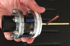
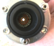
I doubt that Sears and Roebuck could manufacture something with this much quality - this is a pair of bellows that were custom built for me by Dr. Lindsay Wilson. A down-to-earth polymath, Dr. Wilson possesses extraordinary talent and ability that spans innumerable disciplines - a diverse range including but not limited to mathematics, physics, chemistry, computer graphics, machining, engineering-design and manufacture, business, and music. I am indebted to him for his invaluable help in just about every area of science, technology, and beyond.


The ends of the laser tube are nothing more than sections of thin brass tubing that have been inserted into the main glass tube and secured with epoxy. In an effort to maximize the active length of the laser, I refrained from inserting the brass tubing beyond a minimum distance that I felt was necessary to be reasonably secure. However, the bellows will introduce more weight on the ends than I had originally intended. To provide additional support, I decided to make some tube-scope guides similar to those used to secure telescopes.


CO2 Laser 6CO2 laser number 6 is really a continuation of number 3. I continue to revisit this physical section of tubing because its geometry has resulted in what I consider to be truly outstanding performance for a homemade laser:


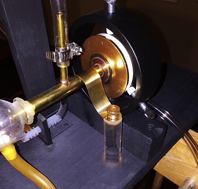
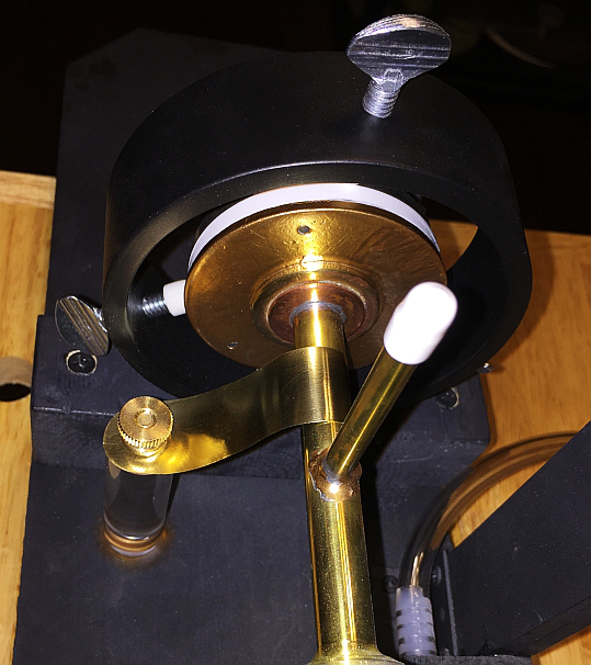
This time, featuring a self-contained gas 'flask', coupling chamber, and conveniently mounted needle valve:


Putting distance between the needle valve and the laser!


It's amazing what torch polishing can do for the appearance of this plastic. The result is astonishing considering that so little effort is actually required.

I found information about this technique by watching a short video clip from Tap Plastics, found here.
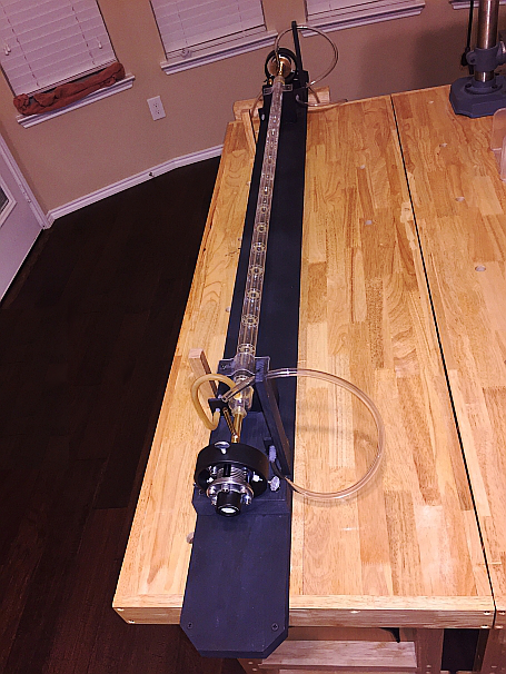
There are a number of easy options for dealing with excess hose, but I wanted to make things look right. I liked the idea of rolling the transparent hose around an acrylic cylinder, and then placing the cylinder around the laser tube - in my opinion, the resulting arrangement was appropriately 'laser-like' in appearance :-)


CO2 Laser 7Here are my plans for an experimental laser to test and possibly confirm my theories over the poor performance of the elegantly aesthetic laser #5. By comparison to lasers #1 and #5, gain will be increased due to the difference in tube diameter and the resonator will be stable due to the radius of curvature of my existing HR. My general expectation is that gain will be a difference between an increase owing to a reduced diameter, and a decrease resulting from a shorter length (I don't know if this results in positive or negative difference, but it's beyond the scope of my goal at this point in time). The current density will be significantly higher; the electric field intensity will be ~330V/cm, requiring around 20 Torr of pressure for optimal performance as opposed to the previous laser which will require an optimal pressure of around 7 Torr based upon its length (~110V/cm). If there's a linear relationship between pressure and molecular density, we might say that we have roughly 3 times as many molecules in the proposed design, at almost 4.5 times the current density! The compact design will best benefit from a heat sink coupled electrode; supported and cooled by a cylinder of water. Flowing water will cool the bore while two additional reservoirs soak up heat from the separate electrodes (three separate parts to ensure good electrical insulation, with flowing water being necessary for the bore only).
Laser #5:
- Current density = 474 A/M2
- Optimal Pressure = 7 Torr
- Active Length = 137cm
Laser #7:
- Current density = 2120 A/M2
- Optimal Pressure = 20 Torr
- Active Length = 45cm


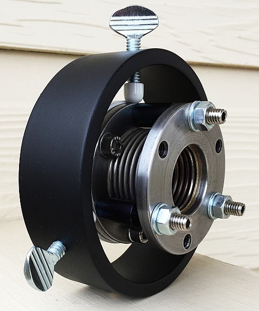
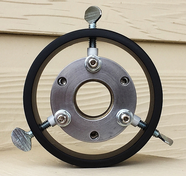
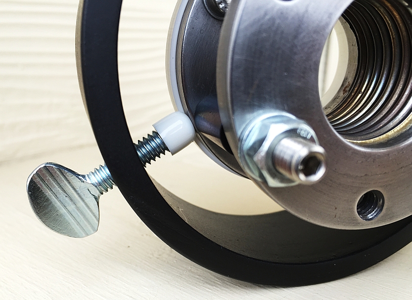
A pair of washers and an O-ring will allow one to tilt the washer with the mirror, while the other washer remains stationary relative to the laser tube. In practice, a series of washers and O-rings would work best. It might be likened to a stack of tires; one on top of the other, resting flat upon the ground - the more tires there are, the larger will be the angle over which one can tilt the top tire when applying downward force at any given point along its edge. The tires can be squeezed, but not like a spring. They are limited in the degree to which they can be squeezed, so more tires will enable a larger range of movement based loosely upon the sum of their individual ranges. One must begin with mirrors that are mounted fairly straight prior to adjustment, or more washers and O-rings will be needed to accommodate the greater angle over which mirrors must be tilted in order to achieve correct alignment.
The following images are virtual representations that I constructed in part with the aid of raster graphics.


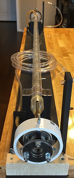
Rather than using washers and o-rings for #7 as depicted above, I decided to cannibalize #5 for its state of the art bellows. The following pictures present the sequence of assembly. I had originally painted one pair of steel washers gold, so that they would approximate the color of the adjacent copper parts. After deciding to use the bellows however, I chose to remove the gold paint. The following eleven pictures were taken before the gold paint was removed. In an attempt to make it look more like the original steel, I colored the washers with a grayish color using post-photograph software (opting for a 'quick-fix' approach rather than taking the time to carefully and realistically change the color using raster graphics). So please pardon the resulting poor quality.


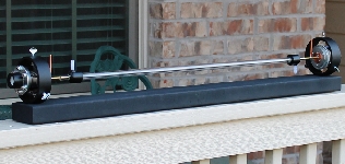
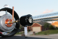
The previous set of pictures was taken with my cell phone camera. The next 7 pictures were taken with a high-quality camera – they feature clear views of the bellows along with the laser tube which is just resting in place (the laser is still a long way from being complete, and the tube has yet to be permanently secured).


Key References:
[1] Professor Mark Csele's Homebuilt Lasers Page


