Requirements:
Dye lasers are optically pumped laser devices which use organic dyes as a host. In basic form, they resemble classic solid state lasers, except the laser rod is replaced with a transparent tube of fluorescent dye.
Unlike many solid state lasers, flash lamp pumped dye lasers require very fast circuitry. Inductance must be minimized by using the shortest possible leads between the energy storage capacitor and the lamp. The leads must also be wide strips, as opposed to single wires. The necessary rise times are best obtained by maximizing voltage, while minimizing capacitance.
Here are some photos of my planned dye cell (tube) and a corresponding flash lamp:
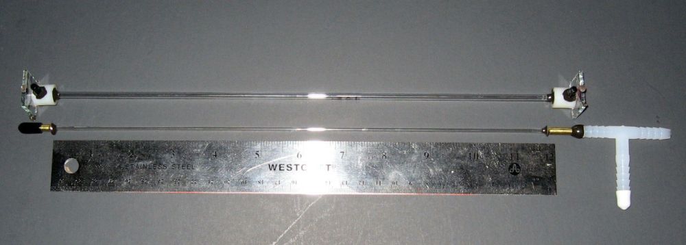
The arrangement consist of two sections of glass tubing. One section is terminated at both ends by short sections of brass tubing. One brass tube is capped (opposite the glass tubing) with an air tight seal. The other brass tube is terminated with a hose barb. The hose barb will be connected to a hose leading to a vacuum pump, through which air pressure within the tubing will be reduced.
The other section of glass tubing is terminated at both ends, by nylon spacers. A hole is drilled through a side of each spacer, and a small hose barb is mounted over each hole. It is necessary to have a hose barb at both ends, because the laser dye must be continuously circulated through the tube while the laser is being used. Such an approach takes advantage of the 'self cooling' capability that is inherit to this type of laser: the host being an actual liquid, as opposed to a solid or gas which must have water flowing around the active medium when cooling is required (for an example, see the water cooling jacket that is required for a CO2 laser).
The outer ends of the nylon spacers are sealed with glass slides (in this case, two sections of anti-reflection coated glass which I pulled from inside an old bar code scanner). The glass slides serve as windows through which the inner cavity beam will pass.
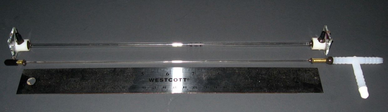
Here is another picture of the arrangement shown above, from a different angle:
About the lamp:
I originally started construction with a single section of glass tubing. I cut the tubing in half, and planned to use one section for the dye cell and the other for the flash lamp. However, I accidentally broke one of the sections, so I used the remaining section of glass tubing for the dye cell. For the lamp, I used a section of cold cathode fluorescent lamp tubing. Such lamps can be removed from inside modern flat-screen monitors. Special attention must be given to the hazards of poisonous mercury, which is contained within these lamps. The phosphorescent coating must also be removed from inside the lamp tubing before it can be used as a flash lamp. The phosphorescent material is also toxic, so all necessary measures must be taken to prevent exposure to all (not limited to the ones mentioned) hazardous materials contained within these lamps. Open one of these lamps, and you do so entirely at your own risks. Do your own research. I have neither knowledge or authority to inform anyone of hazards or health risks associated with these devices.
The phosphorescent material will sometimes become removed when a vacuum source is applied to the tubing. For this purpose, I used a water aspirator (as opposed to a real vacuum pump) during initial testing. By placing my thumb over the end of the tubing, opposite the end to which the vacuum was applied, I was able to remove most of the phosphorescent material by removing my thumb and allowing air to rush in. I repeated this procedure several times until it became clear that the remaining phosphorescent material would require further measures to remove. Here is the section of tubing, with part of the inner phosphorescent coating still intact.
In order to remove the remaining phosphorescent coating, I used a sewing needle and thread. The thread was cut in length to extend just beyond the length of the tubing. At the end opposite the needle, a thick knot was tied in the thread. This knot was soaked in soapy water, and the needle was pulled through the tubing. The soapy knot cleaned the inside of the tube as it was pulled through. Multiple passes were required. In order to pull the needle through the tube, powerful neodymium magnets were placed along the outside of the glass tubing. By dragging the magnets along the outer length of the glass tube, the needle was pulled along the inside of the tubing. The thread was long enough to permit the needle to emerge from the end of the tubing before the knot was pulled into the opposite end of the tube. This thread length was necessary because the knot was required to be large in order to serve the purpose for which it was intended, and therefore required considerable force to pull through the tubing. A picture (below) illustrates the basic setup.
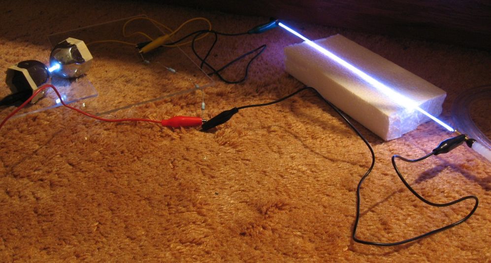
Once the phosphorescent coating was removed, I removed the soapy residue by pulling water through the tube using the water aspirator. Then I was ready for a simple test. I connected the tube to a Leyden Jar capacitor, coupled through a spark gap. I placed a string of four, 1.5 Mega ohm resistors across the lamp. I lowered the tube pressure using the water aspirator, and connected a Wimshurst machine across the Leyden jar. The resulting electrical discharges can be seen in the picture below.